
Experimental motors
Static tests on three solid propellant motors.
 Cleveland State UniversityRocketry Club
Static tests on three solid propellant motors.
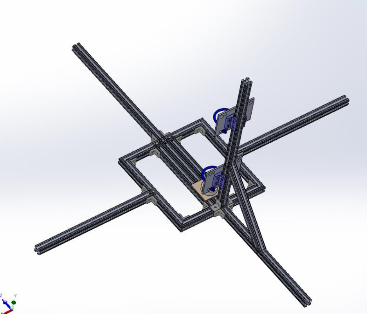
The stand
The test stand must not only withstand the force and temperature of the motor, but it must also serve to protect us from accidental ignitions or other catastrophic failures. There is only one way for these motors to function correctly and countless ways for them to fail.
It will be constructed from 1010 aluminum rail, using brackets to secure the rails to each other. 1010 was chosen for ease of construction or disassembly, and they are lightweight. The motor will be fired into the load cell at the bottom of the vertical rail. The U-bolts will secure the motor to the two sliding rails and prevent any horizontal motion.
The electronics include an HX711 cell amplifier, pressure transducer, Arduino Nano, MAX6675 temperature sensor, HC-12 radio modules, MOSFETs, relays, and the appropriate batteries. To prioritize safety the igniter leads will be broken by a relay and a MOSFET, both of which will need to be in a HIGH state for the ignition to take place. To arm the motor test, a switch will need to be activated from a remote location to activate the MOSFET, and then to ignite the motor another separate switch will need to be activated. Dissimilar redundancy: the relay is a physical switch that is mechanically actuated, and the MOSFET is an electronic switching device that controls current through a semiconductor channel.
The program
So far, we have been successful in launching rockets up to a Level 1 impulse class, and it is now time to take a closer look at the propulsion system to better understand how it works. This will allow us to design and build larger, more precise rockets. Ben Kraft and Abdullah Shariff lead the work.
Our plan is to conduct static tests on three solid propellant motors, with the goal of fully assembling two of them over the next year. One of these will be machined from scratch; however, this will depend on the amount and timing of , as well as the we are able to acquire.
Motor 1
The first motor we will statically fire is a commercial off-the-shelf H-class motor, an Aerotech H195NT-14A. These motors are reliable and produce predictable thrust. This will allow us to test our static test stand while minimizing variables and unpredictability.
By testing this motor first, it will serve as a dry run for our more unpredictable designs. We will be able to test the custom controller and walk through safety procedures while using a known, dependable motor. Another important aspect of this test is validating sensor accuracy and the data acquisition system. The collected data can be compared against known parameters to verify system reliability. Being able to test the stand both physically and electronically will give us confidence and better prepare us for testing more complex and less predictable motors.
Motor 2
Our second motor will be a significant departure from the first. This will be a motor designed for us to test our propellant mixing procedure as we will be packing the propellant ourselves. In an effort to avoid too many variables at a given time, the casing, liner, and closures will be bought as COTS. This way, we can isolate our propellant mixing and packing procedure without also worrying about the structural integrity of the motor.
We will be using a 54 mm case from Aerotech, a 54 mm plugged threaded forward closure, 54 mm casting tubes, and a 54 mm EMK. An estimate of the weight of propellant needed lands just shy of 1 kg. Approximately K-class, with an estimated total impulse of 1,706 Ns.
By testing this motor, we can find issues in our propellant manufacturing process while reducing concerns about the motor experiencing an unplanned rapid disassembly (CATO). This test will provide insight into key propellant parameters such as burn rate coefficient, specific impulse, and propellant density. These measurements can also indicate the presence of air pockets in the propellant, which are known to cause chamber pressure to rise unexpectedly and unpredictably, which is an issue that must be identified and addressed.
Motor 3
For our third and final motor of the year we will aim to use what we learned from the previous tests and put it all together to design, fabricate, and test an experimental motor that will be machined by us in its entirety. While exact dimensions and precise design is not ready at this time, rough parameters can be set. We will aim for this motor to be in the L3 impulse range (5,120 Ns – 40,960 Ns).
OpenMotor will be used to map out predictions of key parameters such as burn time, chamber pressure, and nozzle geometry. Burn time and pressure are important so we understand how long our motor must be subjected to high temperature and can therefore determine the thickness of phenolic needed to protect the casing and the effort that must be made to protect the O-rings. Nozzle throat size is crucial in ensuring that flow reaches choked conditions (M = 1) at the throat while ensuring an adequate diverging section to bring the flow to ambient pressure.
The motor case will be 6061 aluminum with a thickness between 0.125" and 0.25", with generous safety factors knowing aluminum loses about 50% of its strength at just 300 °C. It will be machined to hold a phenolic insulating liner that will erode as the motor burns, limiting heat transfer to the aluminum case. The forward closure will have a port for a pressure transducer and a port for a head-end ignition bolt. Primary and backup O-rings. The aft closure will have room for a graphite nozzle, pasted using RTV silicone sealant. Both closures are secured with radial bolts to hold the shearing load and prevent tear-out from the aluminum casing.
As our experience grows, we can begin researching, designing, and testing more complex propulsion systems, such as hybrid motors. Ultimately, we can reach a point where liquid rocket engines are designed, fabricated, and tested by the CSU Rocketry Club.
On the line
All safety information is based on parameters set by NAR, Tripoli, and referencing how other clubs perform these activities.
A fire extinguisher will always be present at time of test. Testing will take place at a third-party site that is secluded and must be a quarter mile away from buildings in all directions. Anyone participating in the test will be at least 200 feet away at the time of ignition and must not be in line of sight of the motor. Any failure of the motor to light will be treated as a live system for sixty seconds after the failure. No one is in line of sight of the test stand when the motor is armed except one designated safety officer who will insert the ignition lead into the motor prior to ignition.
Propellant
We will be using a slight variation of a well-researched propellant known as Cherry Limeade. This is a propellant designed by the MIT Rocket Team and it has extensive data covering its performance parameters. Numerous other organizations have made Cherry Limeade and subsequently have developed safety protocols for mixing it. Kent State has extensive experience with this process, and we will therefore use their safety precautions and procedures when making this propellant.
Due to the availability of 90-micron ammonium perchlorate, we will be using exclusively 200-micron ammonium perchlorate, which is widely available but will behave slightly differently. It will primarily affect the burn rate as larger particles reduce reactive burn area and also take longer to fully combust, leading to lower performance. This however is not a particular concern for us.
Making propellant produces many risks, both obvious and hidden. Because of these combined hazards, careful handling, protective equipment, and strict attention to procedure are nonnegotiable.
Materials
Three motors, the stand, propellant, and PPE. Electronics for the stand are being bought by a member. Shipping and HAZMAT are not in the figure. Motor 3 is an estimate until the case is locked.